Updated 12-15-2001, PM
OLD RADIO
January 2002 Column

  Return to the Old Radio home page.

A 1927-1929 Tuned Grid Tuned Plate Transmitter
  
Old Radio Column from January 2002 QST magazine. (See magazine for entire article.)

A 1927 TGTP Transmitter

A popular transmitter circuit from the late 1920s was called the "Tuned Grid-Tuned Plate", or "TGTP". The March 1927 QST magazine had a very complete article on this popular circuit, called "A Flexible Transmitter." It was described "as one of the best circuits for short-wave transmission because of its inherent steadiness, efficiency, and ease of adjustment. It can be entirely controlled by two variable condensers, one in the grid and the other in the plate circuit, and is nearly fool-proof."

Another reason for its popularity was its "small size and pleasing appearance," the writer said, "it can be placed in the corner of a small room without undue crowding." He was comparing it to the older, noisier and much larger Spark transmitter of the past......

 
AERO Front View                                    AERO Rear View

When I first saw my transmitter advertised in California, I thought it was an AERO because of the shape. Then I thought it was a Gross because of the coils. Finally I realized it was a homebrew with the best of both designs. I bought it as quickly as I could.....

    Click on the AERO or Gross photos to view "double size."


Click here for an Adobe.pdf file with circuit description and full size schematics - 'AERO'.
      
   
Power Supply as built. There is a bleeder resistor across the load, which is not shown in
the schematic, but is shown in the photo.


Rear view of the homebrew transmitter. The power supply shows tape
holding the filter condensers in place. Actually the redish one is mount-
ed, the rest depend on the tape to hold them in place. It held together
for 73 years!
   
Front view showing the key jack in the center of the lower panel. To its
right is the switch across the key, used for tuning or for AM Phone.


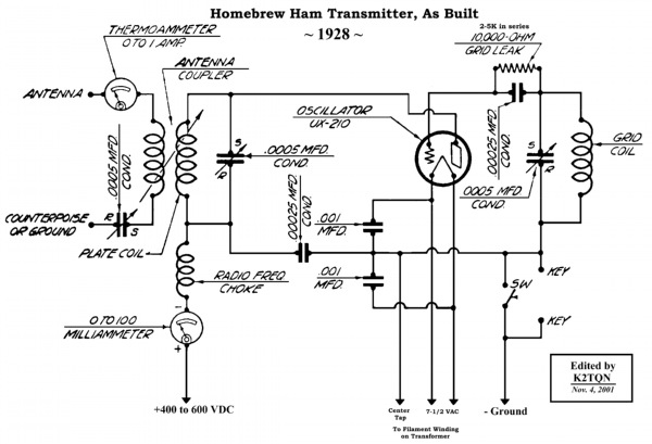
Transmitter Parts List

If anyone builds one of these, please let me know. Email: k2tqn@arrl.net

Lumber list:

Wood type is knot free Hard Pine.
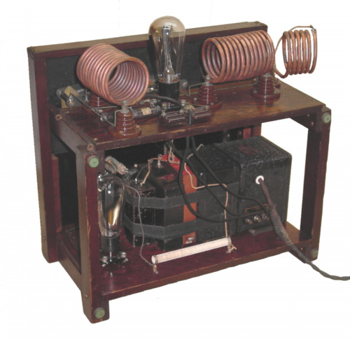
The height overall is 16 inches.
It is 18 inches wide, and 10 inches deep, not counting the front panel.
The top transmitter board is 6.5 by 16.4 inches.
The bottom power supply board is 10 by 16.4 inches.
The four legs are made from 1.5 by .75 pine,
  · Two each, 12 inches
  · Two each 15.5 inches.
Four shelf brackets, 1.5 by .5 pine 10 inches long.
One top piece, 1.5 by .5 pine, 18 inches long.
Fastenings are brass slotted wood screws of the proper lengths,
and the pine boards are pre-drilled to prevent splitting.

Transmitter Parts:

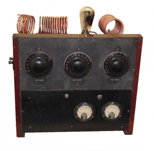
3- .0005 mfd variable condensers
1- .00025 mfd fixed - grid
1- .00025 mfd fixed - plate to filament (High Voltage)
2- .001 mfd fixed - filament to center tap
1- 10 watt 10,000 ohm resistor - grid-leak
1- 0-100 milliammeter
1- 0-1 amp thermoammeter
1- key jack
1- switch
5- 1" standoff insulators
2- binding posts for antenna connection
1- four-pin tube socket, suitable for high voltage
1- Number 10 Globe shaped tube

Coil information:

1- RF Choke wire-wound on ½" wood dowel, or commercial version
All three coils are ¼" copper tubing and have a 2½" inside diameter
  · Grid Coil - 11 turns - 4½" mounting
  · Plate Coil - 13 turns - 5" mounting
  · Antenna Coil - 5½ turns over 2½" with 1 extra inch or so for mounting on one end.

Other items:

2- front panels
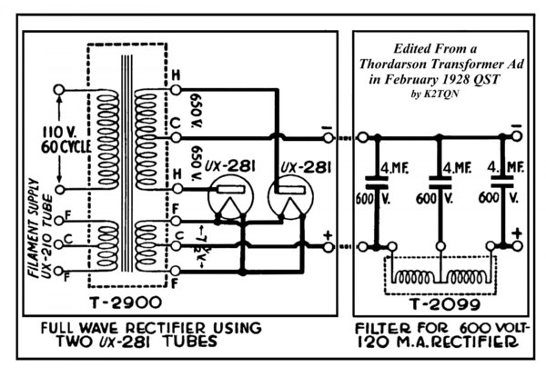
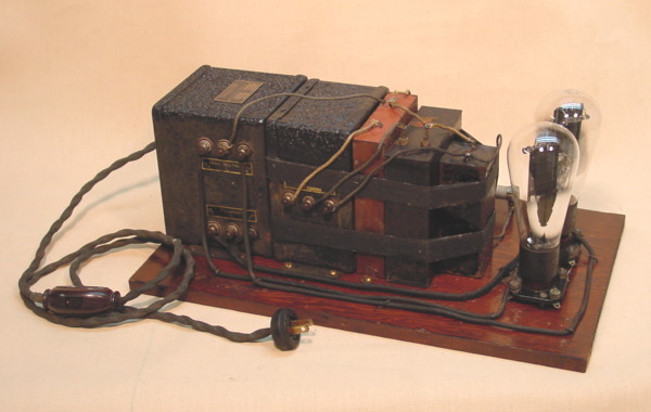
1- suitable power supply
  · 400 to 600 Plate
  · 7.5 VAC Transmitter Filament
  · One other filament winding suitable for rectifier

   
Top view of Transmitter, as wired.


John Dilks, K2TQN    125 Warf Road, Egg Harbor Township, NJ 08234-8501   e-mail: K2TQN@arrl.net