 |
|
|||
|---|---|---|---|---|
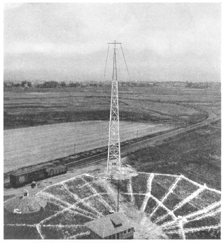
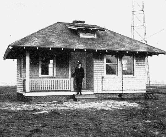
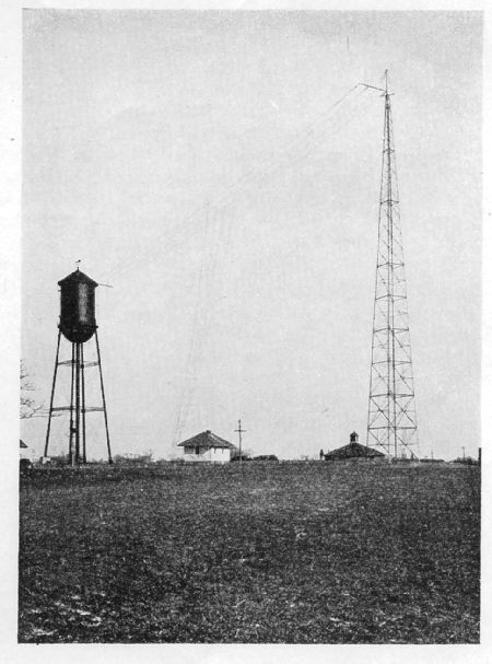
"March 18th, 3:15 A. M. - PJC (Willemstad, Island of Curacao), calls and says our signals very good, through static. (Distance approximately 1,300 miles air line.)" These extracts from the log book of the American Marconi Company's new Cape May (N. J.) station, attest the efficiency of its equipment and operation. The station was opened for service on March 12th. The first Cape May station was built in 1910 atop the Hotel Cape May. A few years afterward another station was erected on a plot of ground owned by the. Pennsylvania Railroad, near the beach. This station was housed by a modest building and a wooden mast, 180 feet in height, was erected. The mast was wrecked by a storm in 1915 and plans for a new station were made.
The transmitter is a Marconi new type panel set, which is employed in shore stations where 6o-cycle -single phase current can be obtained from electric light companies' plants. The spark gap is of the non-synchronous type, with an approximate frequency of 1,100 per second, which gives a high, clear note, different from that of the quenched spark gap. As a result the signals are distinctive and easy to read through interference by other stations.
The transmitter is tuned for three wave-lengths, 300, 450 and 600 meters. By throwing a switch which actuates the primary and secondary circuits and the coupling, changing the primary, secondary and coupling simultaneously, the operator can shift quickly from one wave-length to another. In the case of the 300-meter wave, the operator inserts a short wave condenser in the antenna by opening a jumper which is ordinarily across this series capacity when working on the longer wave. The transmitter can be easily adjusted for any power from 1½ K. W. to 3 K. W., this being accomplished by an adjustable transformer reactance. Ordinarily the set is worked at 2.4 K. W. power, which gives an antenna current of twelve amperes when operated at a wave-length of 600 meters. The installation was under the supervision of the construction engineer of the Marconi Company. Tests with different Marconi stations along the Atlantic coast took place following the installation. |
||||