From Radio News December 1954
 |
|
|---|---|
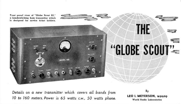
The "Globe Scout 65" transmitter by Leo Myerson, WRL Labs
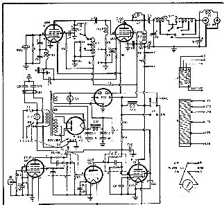
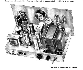
The "Globe Scout 65" transmitter is a general-purpose, 65-watt c.w., 50watt phone, bandswitching transmitter covering 160 meters through 10 meters and designed for the beginning or experienced amateur or as the "second" transmitter for the higher powered group of hams. While designed primarily as a fixed transmitter, it has also been used as a mobile unit by amateurs and CAP groups, since it is merely necessary to pull the jumper plug on the back of the chassis and plug in a d.c. power supply. We suggest the use of a 400 volt, 200 ma. d.c. supply. This transmitter has a 6146 final tube with a 6F6 oscillator using the hot cathode circuit. Complete coverage of 160 through 10 meters is obtained by use of 160-, 80-, and 40-meter crystals. The oscillator stage is easily driven by a small v.f.o. (such as the Lysco model 382). The speech amplifier consists of a 6SJ7 and a 6C5, with a 6L6 as modulator in a combination of Reising and screen-grid modulation which provides ample audio power to fully modulate the final. A high-impedance microphone input is provided. Metering is done in the final grid and final plate. A pi-network antenna tuner with "L" section is utilized in the output to match most types of antennas. The power supply is self-contained. All parts are standard with the exception of the coils and bandswitch which may be purchased from the manufacturer. The oscillator and final coils may also be wound by the builder as follows: Oscillator coil, L2 - 72 turns of #28 enameled wire closewound on 1" form with taps at 45 turns and 61 turns. The final coil, L3, has 82 turns of #22 enameled wire on 1" form with the first 60 turns closewound, tapped at 30th and 60th turn. Then wind 14 turns on ¾" space with tap at 14th turn, then 4 turns on 3/8" space with tap at 4th turn, then another 4 turns on 3/8" space. Circuit Functions Oscillator: The oscillator circuit was primarily designed for crystal operation, although any v.f.o. with an output of 2 to 5 watts will work equally as well. The stage employs controlled regeneration allowing the use of standard 160 to 40 meter crystals and provides more than enough harmonic output to drive the final to full output. Bandswitching is' incorporated in this stage and the cathode keying is crisp and clear on all bands. On straight-through operation, the excitation to the final stage may be in excess of requirements; in· this instance, the oscillator tuning control must be detuned slightly to reduce the amount of drive to the proper level. The oscillator stage is capacity coupled to the final amplifier. R.P'. Power Amplifier. This stage employs a 6146 tube operated as a class C amplifier. Two types of bias are applied to this stage; one is cathode, or self bias, and the other is excitation bias. The cathode of this stage is keyed as is that of the oscillator. The final operates straight-through on all bands except 10 meters where doubling in this stage does not affect the out" put to any appreciable extent. Design of the plate circuit in the final stage utilizes bandswitching plus a pi-network. The pi-network allows matching into various antenna impedances. Speech and Modulator. The speech amplifier circuit is of conventional design, utilizing a 68J7 tube. The amplified speech signal is fed into a conventional 6C5 driver stage through the volume control. Latest components such as printed circuit "Couplates" are utilized; these refinements increase efficiency and ease of wiring. Capacity coupling is utilized between the driver stage and a modified Reising-type modulator circuit. Modification of the original Reising circuit consists of heavily modulating the screen of the 6146, as well as the plate. Metering of either the final grid or final plate circuits is provided with a dual scale meter for constant monitoring of circuit operation. General Information A two screw terminal strip (labeled "Antenna Relay") on the rear of the chassis, provides a 115 v.a.c. source when the transmit switch is in the "on" position. This provides the necessary voltage for an antenna changeover and receiver disabling relay. Operation and Loading A good electrical ground connection to the chassis of the transmitter is essential to efficient operation and proper loading of the final stage. An antenna length of between 60 and 80 feet, at least 15 feet clear of the ground, has been found to be almost ideal for all band operation. A folded dipole type antenna for any band, will match into the pi-section very well, needing no extra matching section. The extra coax connector labeled "Doublet" is used with doublets on the 80- and 160-meter bands, or with antennas on the higher bands (40-10 meters) . Tune up procedure for the pi-section is simple, but care must be exercised so that you do not inadvertently tune to a harmonic of the fundamental signal. The proper tuning point on the final tank is indicated by a sharp, clean and low dip in plate current with the plate tuning capacitor approximately half meshed. When attempting to load with the antenna load control, do not operate with the loading capacitor at minimum capacity as this produces excessive reactance and will lead to excessive harmonic radiation. The loading capacitor should load gradually but firmly from maximum capacity, and should show full load at half of its full capacity. Antenna trimming or lengthening is the obvious remedy for any faulty loading conditions. There are several precautions to be observed when tuning up the transmitter so that proper operation is insured. When tuning the oscillator on the 20-, 15-, or 10-meter bands, two resonance points will be found. One point of resonance is double the 40meter crystal frequency and the other is triple the 40-meter crystal frequency. The doubling resonance point is at approximately ~ full capacity, or when the indicator arrow is toward the left side of its scale. The tripling resonance point is at approximately 14 of full capacity, or when the arrow is toward the right side of its scale. When operating on the 20- or 10meter band, tune the oscillator to the doubling resonance point. When operating on the 15-meter band tune the oscillator to the tripling resonance point. When tuning the final plate control on the 160-meter band two resonance points will be observed. One will be toward maximum capacity or when the arrow is toward the left side of its scale. This is the 160-meter resonance point. The other resonance point is close to minimum capacity of the tuning capacitor, the arrow towards the right side of the scale. On the 15 meter band there are also two resonance points. One resonance point is at 20 meters and will be found at approximately ½ of full capacity. The other and correct resonance point is at approximately ¼ of full capacity or with the arrow facing towards the right side of its scale. Summing up, the tuning capacitor settings for each band are given in Table 1 with the fractions indicating the approximate quantity of full capacity. A long wire antenna is not recommended when operating in a TV fringe signal area. A doublet or folded dipole, half-wave antenna at the operating frequency will give much better results. The long wire, or end-fed antenna, may be used only if it is approximately ½ wave long at the operating frequency. The main objective is to reduce the standing wave ratio on the feed line to a minimum; this will automatically reduce harmonic radiation and TVI. This point cannot be over-emphasized as it is very important in the suppression of TVl and BCl and, at the same time, permits a much better signal radiation from the antenna. A little extra time spent on a properly tuned antenna system will more than repay the operator in better QSO's and less radiated interference. |
|
 |
 |